Make Your Own AVR Board
AVR board is an important development device for many MCU enthusiasts. Sometimes, it can be costly for various reasons. But the good news is, making this board is not too complicated. You can create your own AVR development board with some electronic hobby spare parts from your lab.
Preliminary
To follow this instruction, you need to have basic knowledge of soldering, prototyping with perfboard, schematic reading, and AVR Atmega chips.
How AVR Board Works
Before you make your AVR board, note that you also need a programmer to program your AVR chip. Your board only serves as a medium to place your chip and make connections between it and any peripheral devices or sensors. It cannot program your chip.
The most common programmer used with AVR development boards is USBasp.
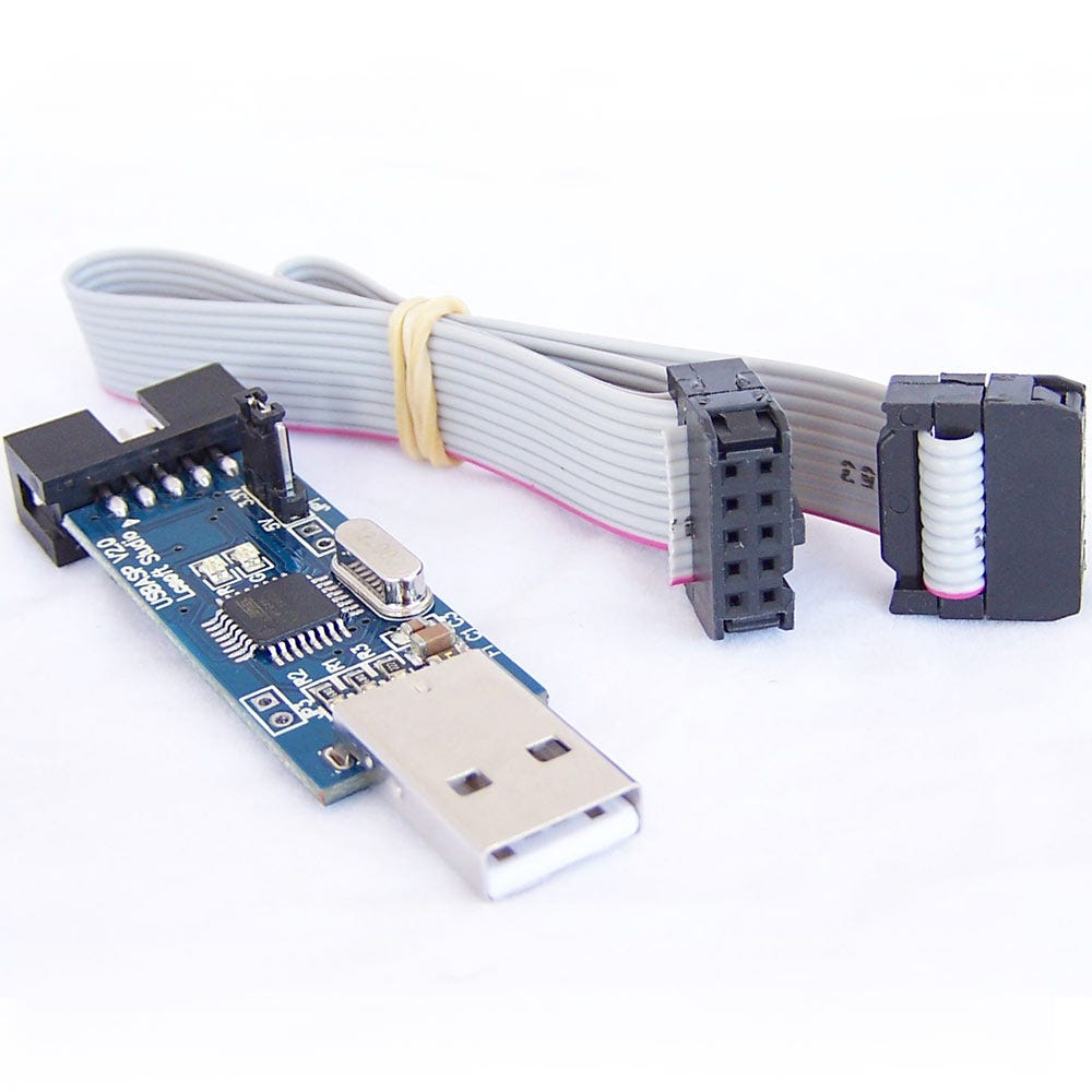
Figure 1: USBasp programmer for AVR.
USBasp Programmer for AVR
USBasp uses the SPI (Serial Peripheral Interface) communication protocol to program your AVR chip. SPI is synchronous communication between two devices to transmit and receive information.
To understand more about SPI communication, you can read this article from SparkFun.
Knowing how SPI works is important. At the very least, you’ll know which pins you must connect to your USBasp programmer. USBasp has 10 pins. We will use several of them to create a connection with your microcontroller so we can program it.
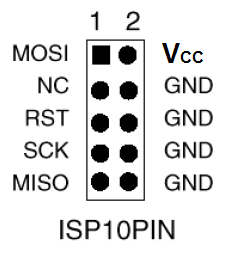
Figure 2: USBaps pins
USBasp Pins Needed:
- Pin 1: MOSI (Master Out Slave In)
- Pin 2: Vcc
- Pin 5: RST (Reset)
- Pin 7: SCK (Serial Clock)
- Pin 9: MISO (Master In Slave Out)
- Any one of the GND pins
With this programmer, you can program AVR chips like Atmega328p, Atmega8A–16PU, Atmega32A, Atmega16A, etc., without installing any bootloader.
Let’s Build Your AVR Board!
After learning a bit about USBasp, it’s time to prepare the materials for this project.
Materials:
- 1 Perfboard (7x5 is recommended)
- 1 DIP 28 IC Socket
- 1 AVR microcontroller (e.g., Atmega328p)
- Several male pin headers (preferably 1x40 strips)
- Jumper wires
- 2 Ceramic capacitors (22 pF)
- 1 Oscillator (16 MHz)
- (Optional) 1x3 female pin header (rounded ones are better)
Note: A soldering iron and soldering lead are mandatory. A hot glue gun is also recommended to secure your soldering.
Let’s Make a Short!
This schematic will give you an idea about the AVR board you’re going to build. We use Atmega328p here, but you can also use Atmega8–16PU. If you use a different Atmega version, refer to its datasheet for pinout information.
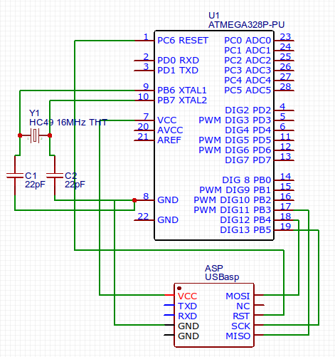
Figure 3: The schematic.
The Schematic
The schematic includes basic connections for your AVR board and covers the important wiring required to connect your AVR chip with the USBasp programmer.
Required Connections:
- Connect USBasp MOSI to AVR pin 17
- Connect USBasp MISO to AVR pin 18
- Connect USBasp SCK to AVR pin 19
- Connect USBasp RST to AVR pin 1
- Connect USBasp VCC to AVR pin 7
- Connect USBasp GND to AVR pin 8
- Install the oscillator to pins 9 and 10 of Atmega328p
You also need to install the oscillator to pin 9 and 10 of your Atmega328p.
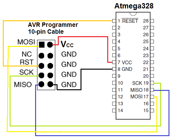
Figure 4: Another reference you can follow
Let’s Solder It Down!
I won’t say you must follow exactly how I solder my AVR board — soldering is an art you should express in your own way. 😄
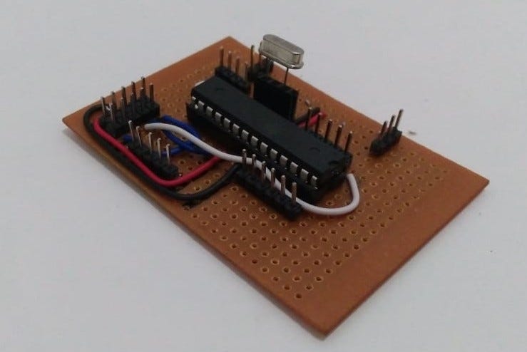
Figure 5: My AVR board.
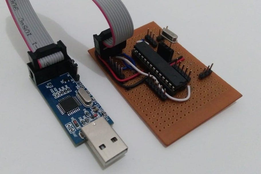
Figure 6: Connected with USBaps.
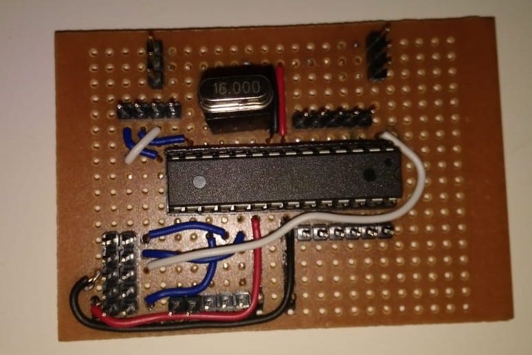
Figure 7: My AVR board from top view.
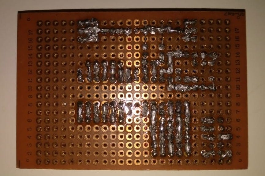
Figure 8: The soldering part (sorry if this looks messy and irritating for you ☹️ )
But here are some recommendations to make your AVR board more versatile:
My AVR Board:
- Connected with USBasp
- Top view of my AVR board
- Soldering part (sorry if it looks messy!)
Recommendations:
- Use a female pin header for your oscillator so it can be changed easily.
- Create a Vcc and GND strip using 1x3 or 1x5 pin header for future power needs.
- Connect every DDR port to a pin header for I/O usage in your programs.
- You can use either male or female pin headers depending on your preference.
That’s all I can share with you this time. If you have better ideas for this project, please feel free to leave a comment.
Hope you found something new and useful. Stay curious. 🙂
 ahmadtheswe blog